
 |
Eager Space | Videos by Alpha | Videos by Date | All Video Text | Support | Community | About |
|---|

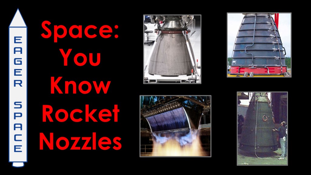
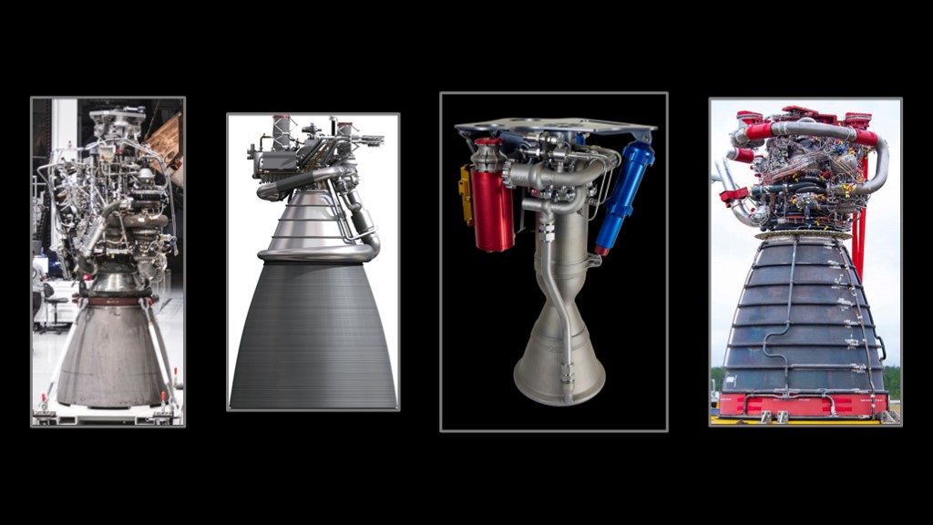
Looking at rocket engines, the first thing we notice is all of the complex plumbing at the top of the engine - usually known as the "powerhead".
But the nozzle at the bottom is equally important in building an efficient engine, and that's our topic for today.

Let's start with combustion in the open air. All of the particles that comes from that combustion go in a different direction, and there's no net force. Not a very good rocket engine.

If we wrap that combustion in a chamber with a hole on one side, we force all the particles to come out mostly in the direction that we want them to come out, and that gives us a net force in the direction that we want. It's better but we're wasting a lot of energy with particles going to the side.
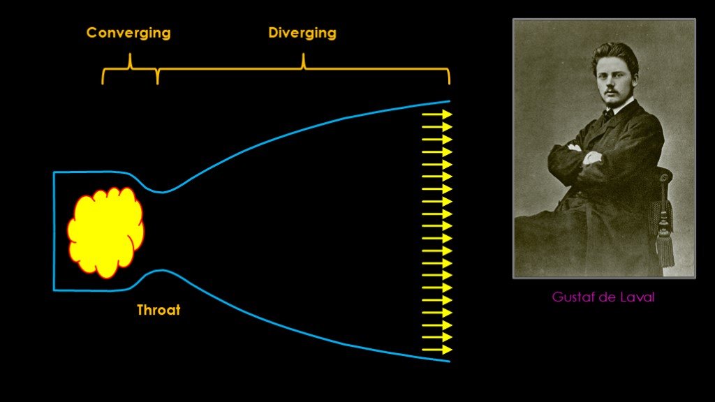
What we need is some sort of device to get all the exhaust going in the direction we want, and that device is a nozzle.
This design is known as a "bell nozzle" because it's shaped like a bell, and it's the most common design for liquid-fueled engines.
It's technically known as a "de Level" (day le val) nozzle, invented in 1862 by Swedish engineer and inventor Gustaf de Laval (day le val) for use in steam engines.
The nozzle converges into a tighter throat and then diverges out as the nozzle gets larger, so it's also known as a "converging diverging nozzle.
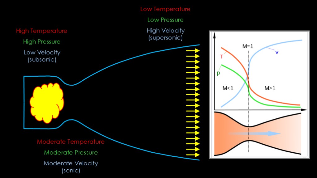
There's something more complex going on that I'd like to touch on briefly in a simplified form as the physics is fairly complex.
In the combustion chamber we have the highest temperatures and pressures, which makes sense, as that is where the combustion is taking place. The velocity is what is termed as "low" which means less than the speed of sound.
The constriction of the throat results in a reduced temperature, a reduced pressure, and an increase in velocity, up to the speed of sound.
After that, the expanding nature of the nozzle results in a drop in temperature and pressure and an increase in velocity.
Here's a nice little graph from Wikipedia that shows how the pressure and temperature go down and the velocity goes up a lot.
This velocity increase is one of the main jobs of a nozzle - the faster our exhaust velocity, the less fuel our engine uses to generate a specific amount of thrust.
And therefore, the more you can expand the exhaust, the higher the velocity, and the better your engine works.
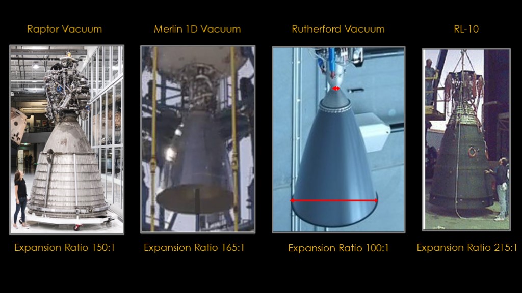
Let's look at some engines.
This is the Rutherford vacuum engine used on Rocket Lab's Electron rocket. You can see that the throat of nozzle is really tiny, and the exit of the nozzle is really big. We can divide the area of the nozzle exit by the area of throat to calculate the expansion ratio, sometimes called the area ratio. Rocket lab doesn't publish the expansion ratio, so I've estimated it at around 100 to 1.
The Merlin 1D vacuum used on SpaceX's Falcon 9 second stage has an expansion ratio of 165:1.
The Raptor vacuum is slightly less at 150 to 1.
And finally, we have the RL-10, used as the upper stage on the Atlas V from ULA and on the SLS upper stages. It has an expansion ratio of 215 to 1.
All of these engines use high expansion ratios because that will give a high exhaust velocity and therefore a high efficiency.
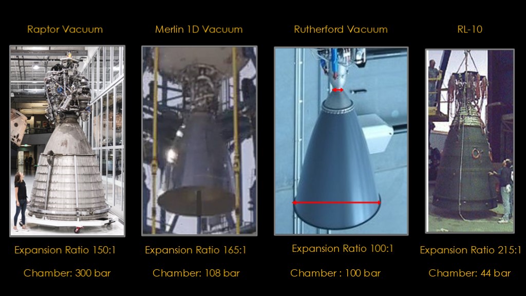
Expansion ratios can be a bit misleading, because what we really care about is the actual pressure at the nozzle exit, and that depends on the chamber pressure, the expansion ratio, and other factors. Calculating the pressure is left as an exercise for the student.
I do think it's interesting to look at the chamber pressures to get a relative sense of the impact.
Raptor probably runs at around 300 bar, or 300 times atmospheric pressure, which is ridiculously high. Even with a big nozzle the exit pressure is higher than you might expect.
Merlin 1D and Rutherford run at around 100 bar.
The RL-10 runs at a very low chamber pressure of only 44 bar, so that combined with the high expansion ratio yields great efficiency. And there's a version of the RL-10 with a two-part nozzle that runs all the way up at 285 to 1, for even more efficiency.
The obvious question is "why don't the other three have bigger nozzles?", and the answer is "weight, packaging, and price". Bigger nozzles need to fit inside the rocket stage and not be too long, so it's a tradeoff. And price is something you would like to minimize - the RL-10 is a great engine but it will cost you more than $15 million a copy.
Generally with vacuum engines you fly the biggest nozzle that you can make fit.
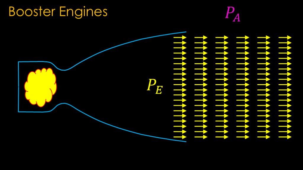
Booster engines - the engines used on the first stages of rockets - have a different set of constraints.
Not only do we want a low pressure at the exit, we want to want to keep that nice ordered flow after the nozzle. There's a simple condition that we need to keep that happening - we need to set the exit pressure of the nozzle to be equal to the atmospheric pressure outside the nozzle.
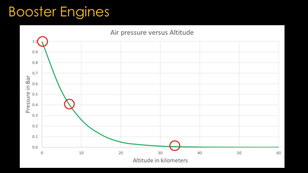
And here's the problem.
Our booster engines start at full atmospheric pressure, at 1 bar. A minute later they are at 7 kilometers of altitude and pressure is down to 0.4 bar, and after two minutes they are 33 kilometers up and pretty much in a vacuum. There's simply no way to build a bell nozzle that is optimized at those different pressures.
We learned that vacuum nozzles were the most efficient, so lets see what happens if we choose a vacuum nozzle for our booster.
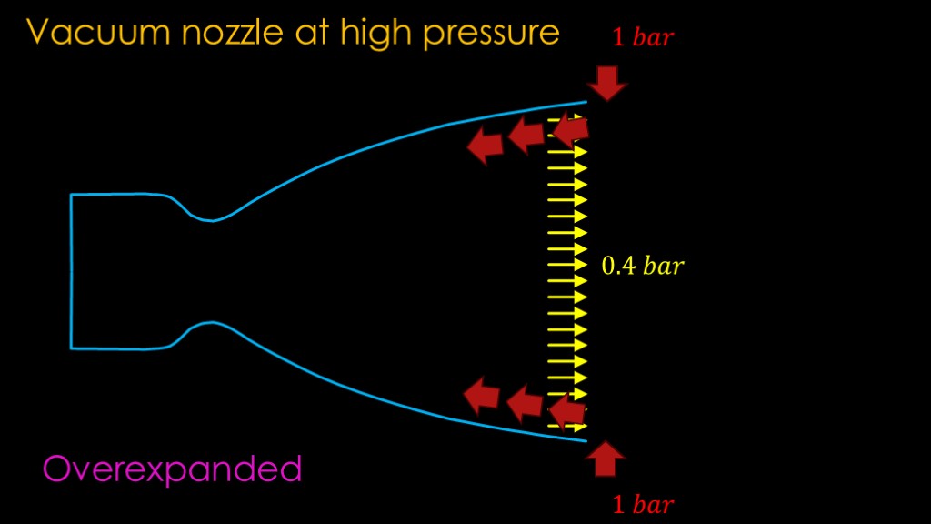
Let's say we're running our vacuum nozzle at sea level. It has a low pressure, let's just say it's 0.4 bar. The atmospheric pressure outside the nozzle is 1 bar, and that high pressure allows a reverse flow of air to creep up inside the nozzle.
The term for the situation is "overexpanded" - the nozzle expands the exhaust more that the optimal amount to match the outside air pressure.

Here's a simulation of the what happens. First, you can see that the smooth flow is detached from the wall of the nozzle - this is known as flow separation. It results in chaotic shock waves inside the nozzle.
This is a serious case of flow separation that will break pretty much any engine.
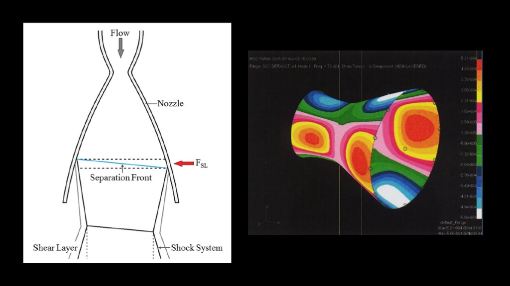
The asymmetry in the nozzle causes side forces to be created in the nozzle, and those forces cause the nozzle to deform. Here's a view of the forces on the nozzle from NASA experiments.
But it would be really nice to have a more visual representation.
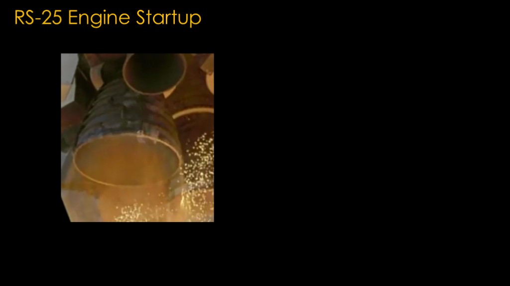
Luckily we have the space shuttle main engine or RS-25.
What isn't commonly recognized is that all booster engines are prone to flow separation at engine startup because the pressure is always low during startup - they always start up overexpanded. This is one reason it is hard to start up engines smoothly.
In this video, concentrate on the inside of the nozzle. The bright lines that you see show the areas in the nozzle where the flow is separating. It's very chaotic and the flow separation doesn't go away until the engine is at full power.
The second video is the same sequence at a higher rate. Watch the rim of the exhaust nozzle during this sequence. The side forces from the flow separation are deforming the nozzle bell and it is "ringing" until the thrust is high enough that the flow separation goes away.
Flow separation limits how big of a nozzle we can use at sea level.
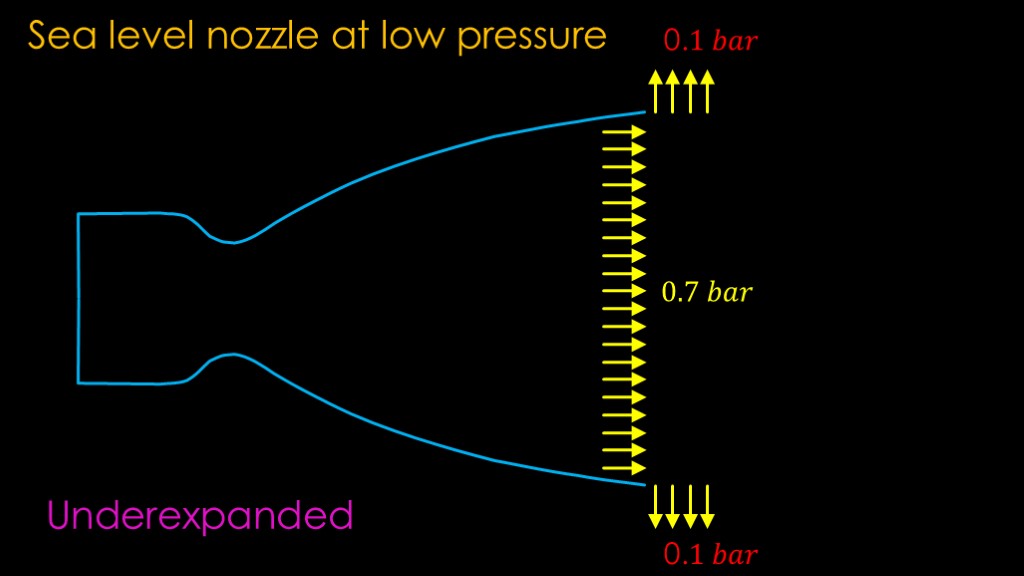
If we have a nozzle optimized for sea-level performance running at low pressure, we have the opposite problem
Our nozzle produces exhaust at a pressure of 0.7 bar, but the atmospheric pressure is much lower, at only 0.1 bar.
When our exhaust flow hits the edge of the nozzle, it encounters that low pressure and it immediately wants to spread out to the side rather than continuing in the direction that we want it to go.
This is known as "underexpanded" - our nozzle is too small and therefore our exit pressure is too high.
Other than the loss of efficiency, underexpanded operation does not cause problematic issues the way overexpanded can lead to flow separation.

We can see the effect of different atmospheric pressures very clearly by looking at a launch.
The Falcon 9 burns a refined version of kerosene known as RP-1 and that makes its exhaust plume very visible. Let's look at a launch.
(narrate)
There's no way to build a bell nozzle that works optimally for a booster. But it turns out that nozzle efficiency isn't the most important factor.
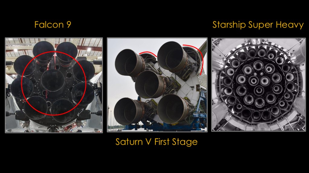
There is, however, another big concern that drives the size of the nozzles on booster engines.
This is the bottom of a Falcon 9 booster stage. Note that the engines are pretty tightly packed.
This red circle is the size of the Merlin Vacuum nozzle, and it's pretty clear that there is only room for one engine.
For boosters, you need high thrust to be able to get off the pad, and the small nozzles on the Merlin 1D engine make it possible to fit 9 engines in a small diameter.
You see this same decision at work on the starship super heavy booster - the engines are sized to fit 33 of them underneath the booster.
And lest you think this is just a spaceX thing, these are the F-1 engines on the base of the Saturn V booster. The nozzles are just a little bit too big to fit inside the diameter of the first stage so there are small fairings around each of the outside engines.
Total thrust matters much more than efficiency for boosters.
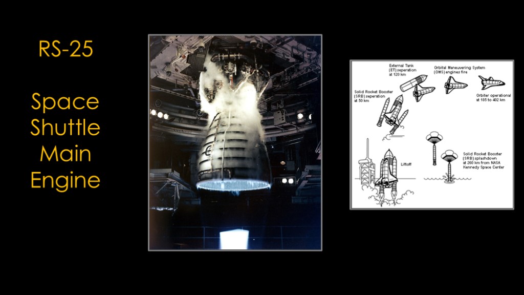
And that brings us to a very weird engine, the RS-25 Space Shuttle Main Engine. It's a weird engine because the shuttle was a weird vehicle, one that starts its engines at sea level and runs them all the way to orbit.
The engine needs to work efficiently in vacuum because most of the launch is in vacuum, which means it needs a big nozzle but that nozzle also needs to work at sea level.
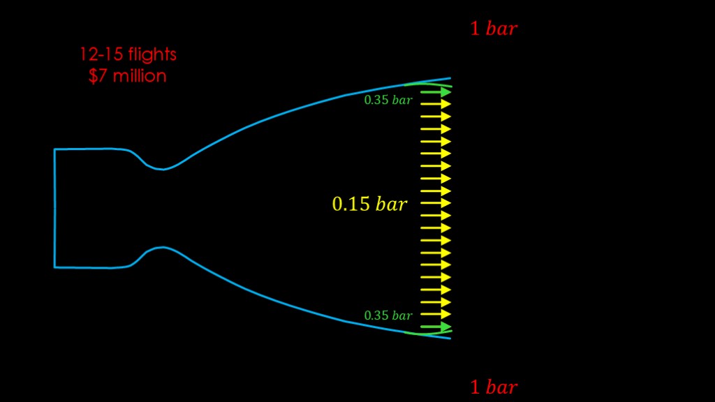
The target pressure for the main exhaust was about 0.15 bar, low enough to give decent performance in vacuum. But that was too low to prevent flow separation.
The fix was to slightly change the nozzle right near the exit, changing the rim so that it curved back in. That produced a small layer of exhaust at about 0.35 bar, and that was just enough to make the engine avoid flow separation.
But it's not all great.
The movement that we saw on the videos caused damage to the nozzles, and they were only good for 12-15 flights before they needed to be replaced at a cost of $ 7 million in 1999 dollars. NASA did have a plan to use a different design with more longevity but never got around to building it.
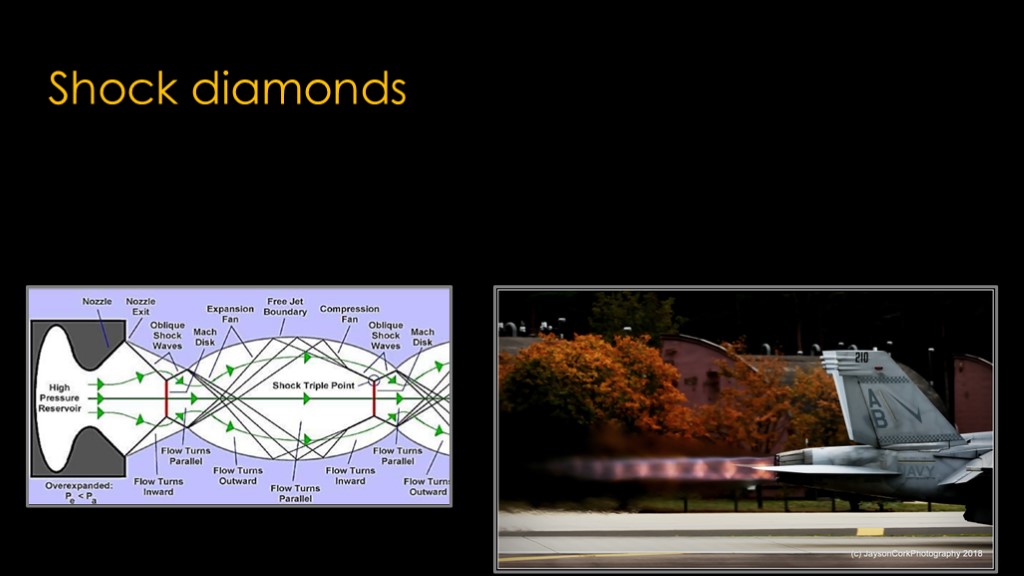
Here's a cool nozzle-related phenomena
These are known as "shock diamonds"
It's commonly believed that this is a sign of a powerful or efficient engine, but it's actually just a sign that that the exhaust pressure doesn't match the outside air pressure, which we know is very common with booster engines at sea level.
There's a lot of fun physics you can dig into if you want, but it's hard to deny that it's a pretty phenomena.
Shock diamonds show up in jet engine exhausts for the same reasons - jet nozzles are designed to be most efficient at a higher altitude than sea level.
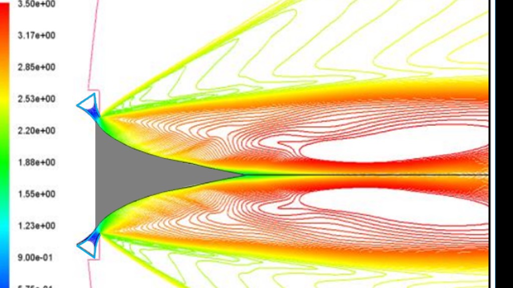
There's an interesting alternative to the Bell Nozzle...
You start with a shape that is a cut-off spike
Then you add in a combustion chambers in a ring around the shape so that the exhaust gases go against the curve, confining them on that side.
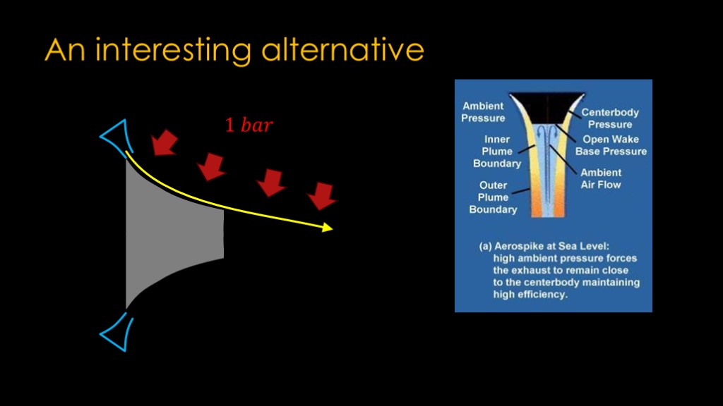
If we run this engine at sea level, we have 1 bar of air pressure pushing against that stream of exhaust gases, and that keeps it next to the curve and - more importantly - allows it to expand until the exhaust gases hit that 1 bar of pressure.
That's the pressure we're looking for to get the most efficiency.
Here's a diagram with some more detail. This design is known as an "aerospike", and at sea level it will direct the airflow in the direction we want.
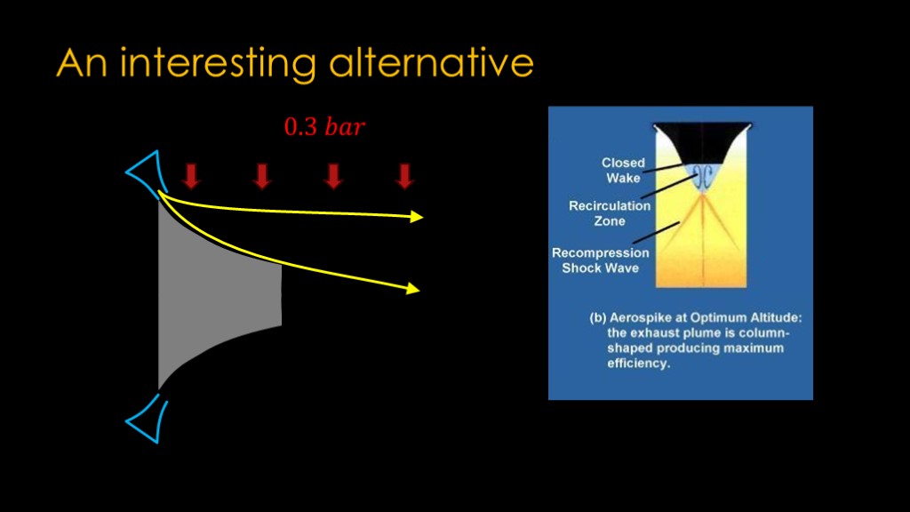
As our rocket gains altitude, the outside air pressure drops. That allows the exhaust plume to expand to equal that air pressure, once again giving us exactly what we want in terms of a nozzle.
This is the "design altitude" of the aerospike, giving us optimal efficiency.
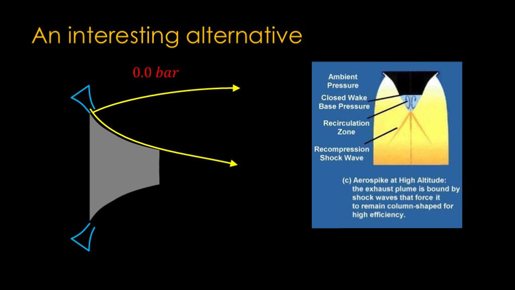
In vacuum, we end up with no air pressure to help shape the expansion. Some of the shock waves coming off the central area help keep the efficiency good.
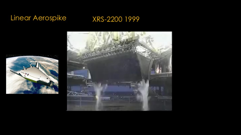
There's an interesting variant known as the linear aerospike. This particular engine is the XRS-2200 build by Rocketdyne in 1999 as the engine for the X-33, prototype for the VentureStar single stage to orbit craft.
Here's a video.
You probably noticed that there are a series of small combustion chambers next to the central wedge, 20 of them on each side.

Aerospike engines sound like a great idea, and they are media darlings - you can find numerous breathless articles saying how revolutionary they are.
What's the reality?
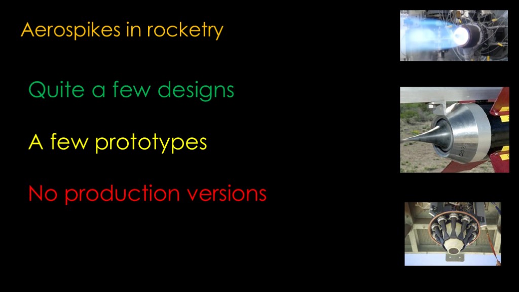
If we look into the details of aerospikes in rocketry, here's what we find.
Quite a few designs
A few prototypes
No production versions
That is a general sign that something is not as great as the advocates think it is.
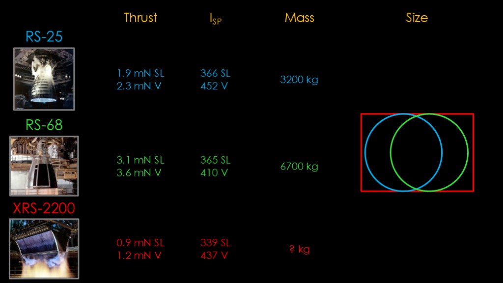
Let's look at three engines to see if we can garner some useful information...
The RS-25 flew on the space shuttle and now flies on SLS.
The RS-68 flies on the Delta IV
The XRS-2200 was built for the X-33 project.
All of these engines burn liquid hydrogen and liquid oxygen.
We'll start with thrust. The RS-25 puts out 1.9 meganewtons of thrust at sea level and 2.3 meganewtons in vacuum. The RS-68 is a big brute of an engine, with 3.1 meganewtons at sea level and 3.6 in vacuume. The XRS-2200 comes in at 0.9 meganewtons at sea level and 1.2 in vacuum. It's about half the thrust of the RS-25 and a third of the RS-68.
Looking at efficiency, the specific impulse of the RS-25 is a very nice 366 at sea level and 452 in vacuum. The RS-68 gets 365 at sea level and only 410 in vacuum. The RS-68 uses a gas-generator design rather than the advanced staged combustion design used by the RS-25, and it's also designed as a booster engine with an expansion ratio of only 22 to 1, so we would expect the RS-25 to be better in vacuum. The XRS-2200 gets 339 at sea level and 437 in vacuum.
This is frankly disappointing - the whole point of going with an aerospike is to get better efficiency and the XRS-2200 is roughly equal to the RS-68 and considerably behind the RS-25.
Looking at mass, the RS-25 is 3200 kilograms, the RS-68 is the big beast and 6700 kilograms, and the XRS-2200 is.. Unknown.
Try as I might, I couldn't find any mention of the mass of the XRS-2200. We can't really conclude anything from negative data, and you can draw your own conclusions about what the lack of data might mean.
Finally, if we look at the size of the engine, the RS-25 is 2.4 meters in diameter and interestingly, the RS-68 is also 2.4 meters in diameter. The XRS-2200 is rectangular and a bit larger in area than the other two.
What have we learned? Well, the XRS-2200 isn't very exciting. It doesn't put out very much thrust for the space it takes up and the high efficiency that we were hoping for doesn't appear to be present.
There was a larger RS-2200 planned that would supposedly produce similar performance to the RS-25 but come in a larger package. It of course was never built so it's not really a fair comparison to these engines.
And that's the story of aerospikes. They seem like a great idea but nobody has every built a production aerospike engine, and there's probably a reason for that.
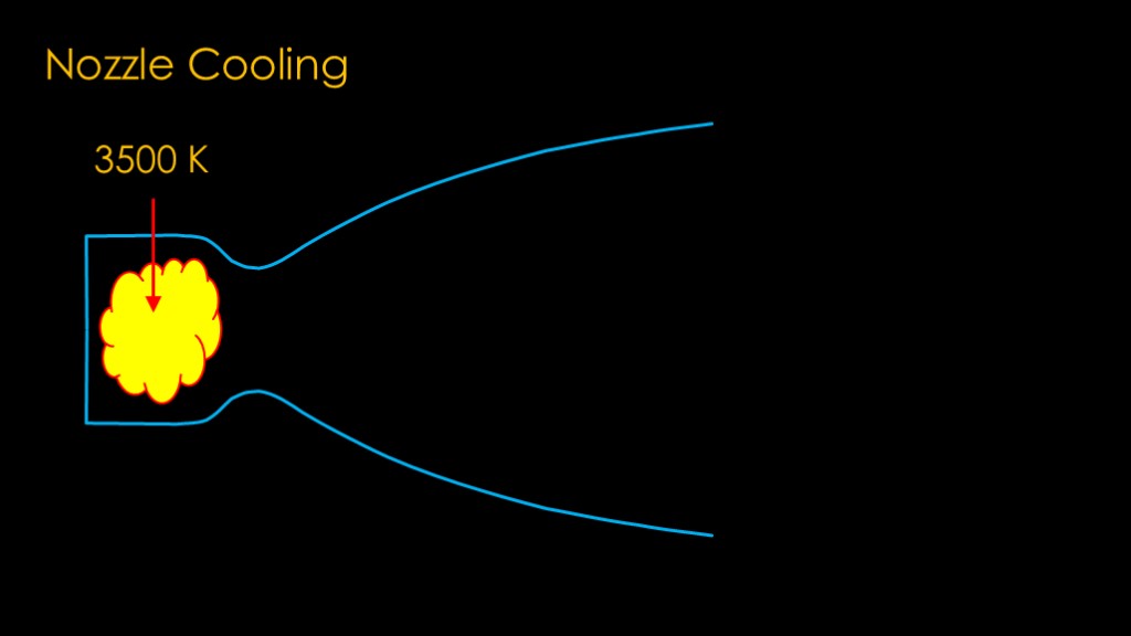
We're now going to switch gears and look at nozzle cooling.
Our combustion chamber presents a bit of a problem. The combustion temperature is about 3500 kelvin, which is very very hot, and we need a way to keep the metal parts from getting all melty.
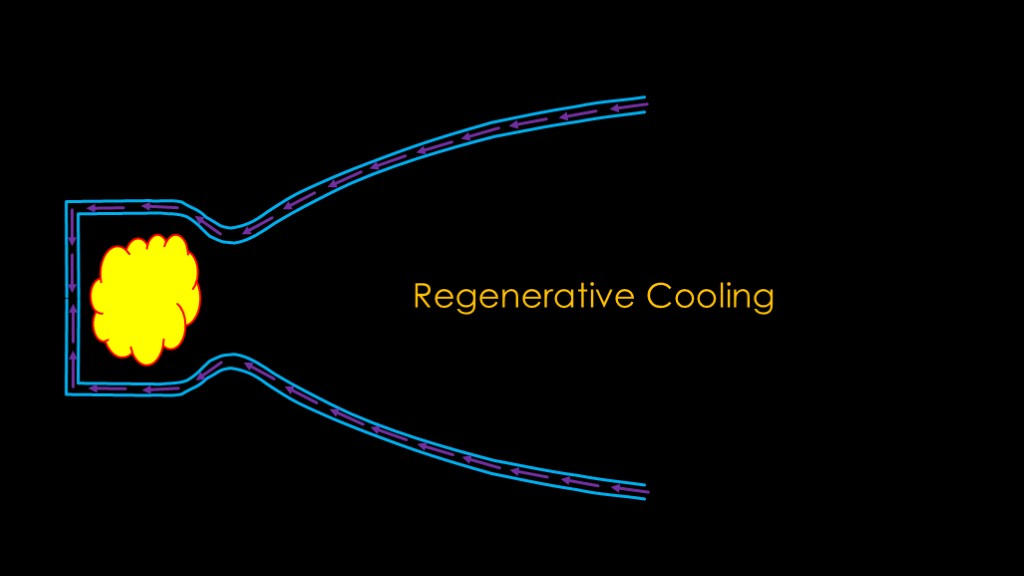
To deal with the heat, we're going to build our nozzle so there is an inner and outer wall and then we will flow one of our propellants between the two walls to carry the heat away. That hot propellant is then fed into the combustion chamber.
This is known as regenerative cooling and is a very common technique.
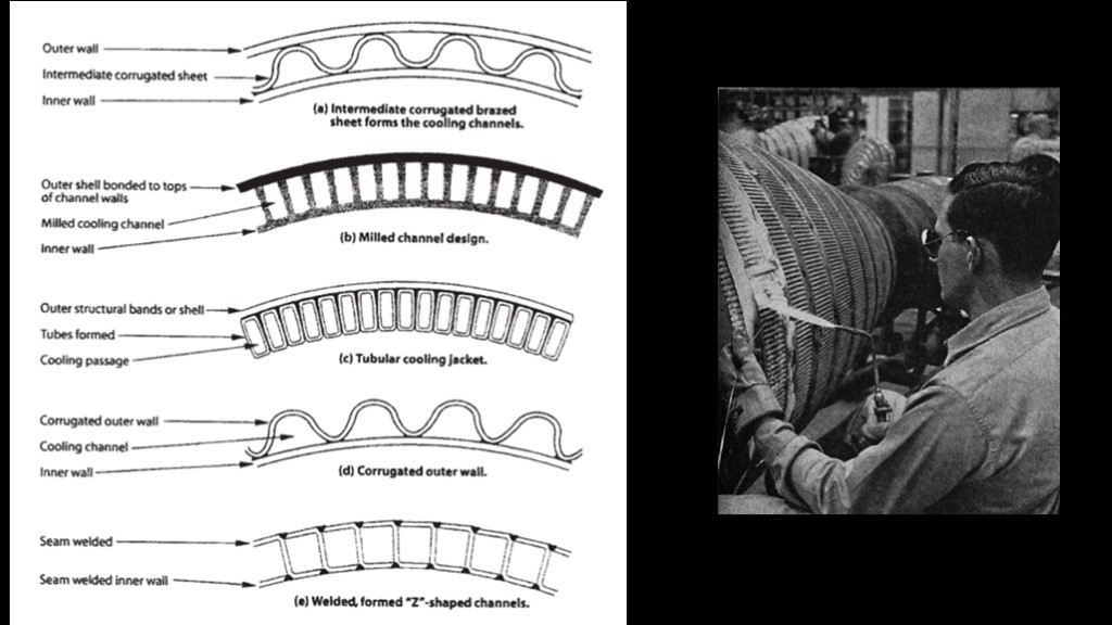
There are many different ways of building the dual wall nozzle with the cooling channels. Traditionally, they were made of individual pieces of tubing that were brazed together, but modern engines use techniques that are quicker and cheaper.
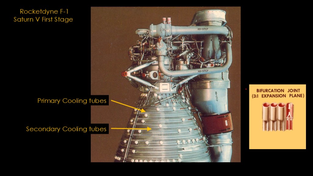
We can see this in a real engine. This is the upper part of the rocketdyne F-1 used on the first stage of the Saturn V.
The upper part of the nozzle is composed of the primary cooling tubes, and slightly below that, each primary tube splits into two secondary cool tubes.
The cooling is accomplished by a flow of RP-1 fuel down the nozzle. RP-1 is used rather than liquid oxygen because hot oxygen doesn't play well with others. At the bottom of the tubes, the fuel is collected and sent back to the top of the engine to be burned.
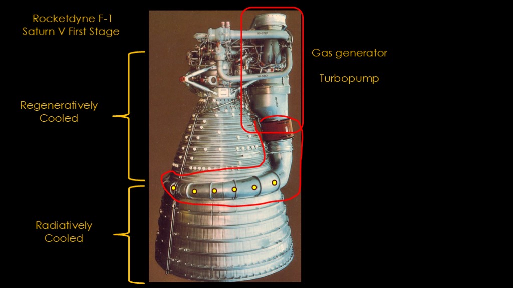
I deliberately hid the bottom part of the engine in the last slide. Below the section of the nozzle that is regeneratively cooled by fuel flowing through tubes there is a nozzle extension that is radiatively cooled. It's made of stainless steel and it gets rid of heat by heating up and radiating the heat away. As long as the temperatures aren't high enough to exceed the strength limit of the material, radiative cooling works fine.
But what is the weird wormy thing that's wrapping around the nozzle?
On the top-right of the engine we have the gas generator, which is a small combustion chamber that produces gas to drive the turbopump that pumps the propellants into the main combustion chamber. Gas generators run at lower temperatures than the main combustion chamber because the turbines cannot withstand high temperatures and therefore their output exhaust is also at a low temperature.
The gas is piped into the duct that wraps around the nozzle and injected into the nozzle through holes spaced around the nozzle.
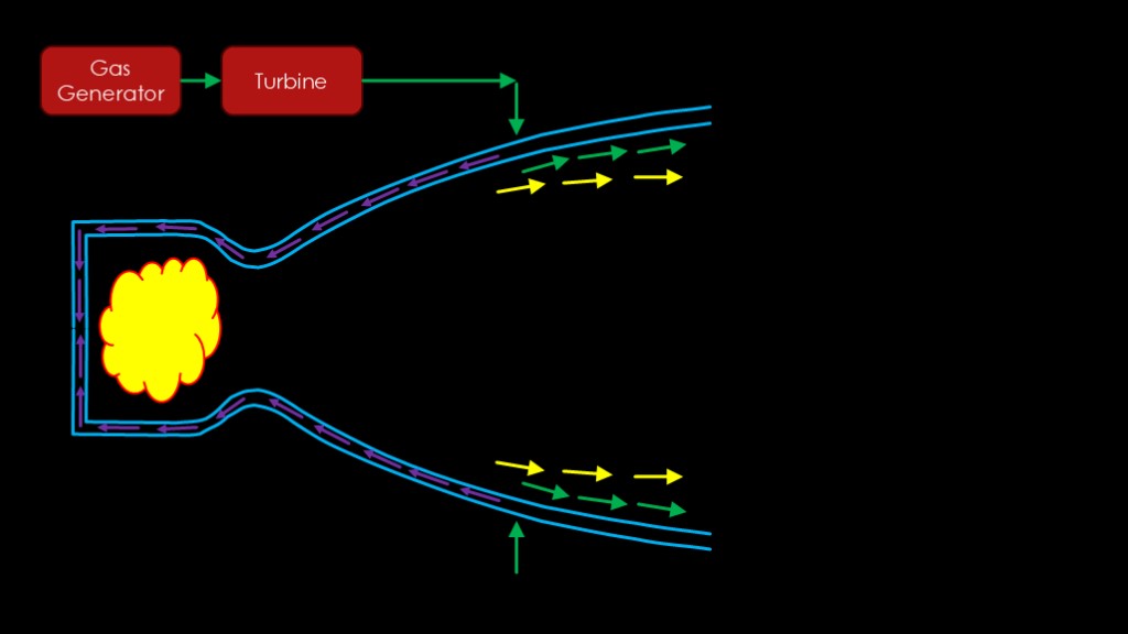
The gas generator generates gas to drive the turbine, and then the leftover exhaust is injected all around the nozzle.
The gas forms a film between the nozzle and the hot gas from the combustion chamber, and this technique is therefore known as "film cooling".
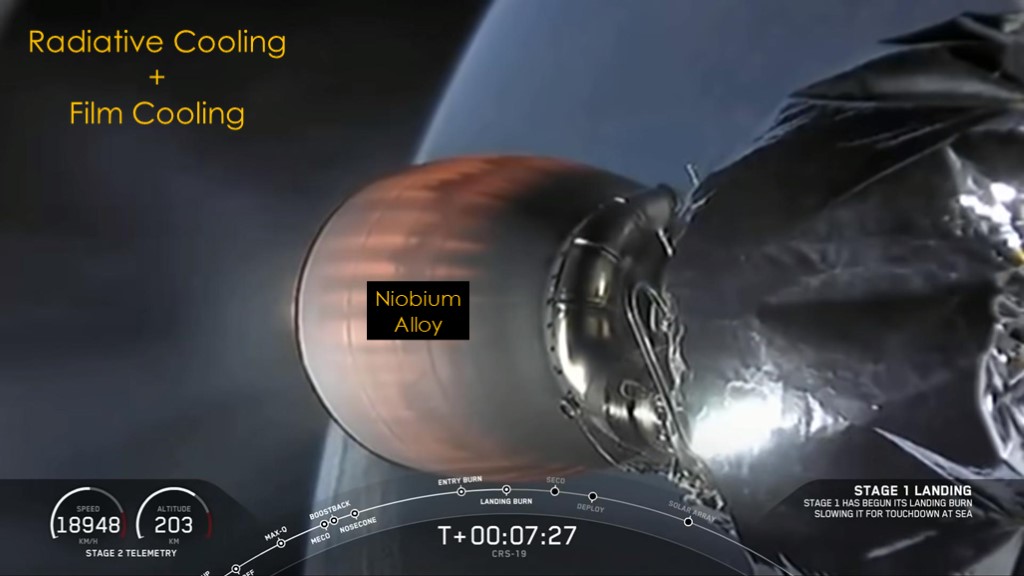
If you've seen a Falcon 9 launch, you've seen this same technique in action on the Merlin vacuum engine - the output of the turbopump is injected in the nozzle to help keep it cool.
Like the F-1, the nozzle extension is radiatively cooled, but in the merlin it is made of a niobium alloy that is very heat resistant and is therefore fine even when it is red hot.
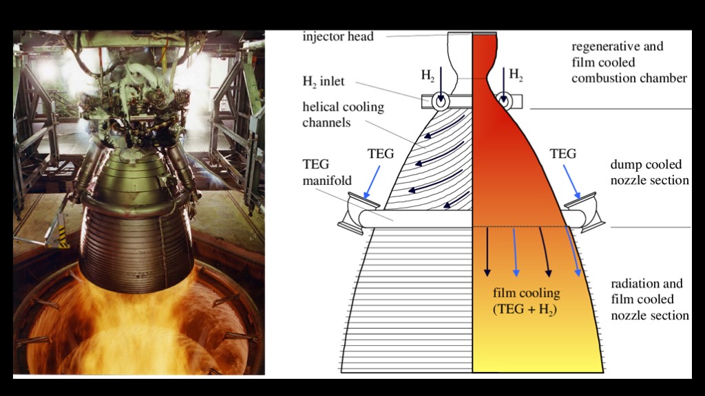
The Vulcain 2 engine used on the Ariane 5 also uses the same approach.
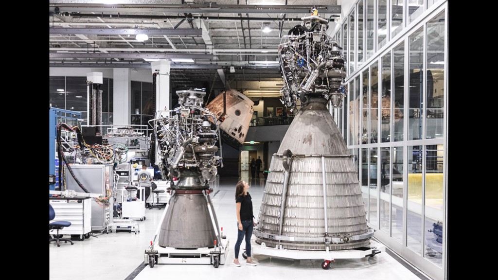
More advanced engines like the SpaceX Raptor used on starship do not use gas generators so there is no handy exhaust to help cool the nozzles.
However, it is still possible to use film cooling by injecting a small amount of liquid methane fuel around the nozzle.
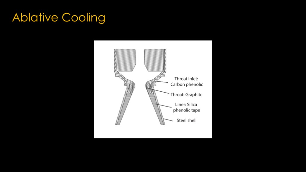
A final cooling technique is ablative cooling, where the nozzle is lined with a material that will slowly burn away as the engine fires - very much like a heat shield on a capsule returning from orbit.
This is very common on solid rockets where there is no handy liquid to use for regenerative cooling, though it has been used on some liquid cooled designs.
And now, you know rocket nozzles.

If you enjoyed this video, please send me a Marycan hose nozzle including such features as:
Metal gun body
The metal handle
Encapsulates the knob
Saving card buckle
Package glue gun
And the all important "the pacifier"